

Introduction
Due to the utmost importance of the Cathodic Protection System in preserving the integrity of the prestressed concrete piping system, the Authority implemented a cathodic protection system for the entire course of the Man-made River with a length of 4000 km, and the following facts reflect the extent of the system's size:
• The surface area of the concrete pipes protected by the system is about 50,285,714 square meters.
• The amount of current used in the cathodic protection is about 62,857,143 mA.
• The amount of zinc used in cathodic protection is about 27,000 tons.
• The length of the main copper electrical cables used in cathodic protection is about 8,000 km, with an average cross-section area of about 70 square mm.
• The number of control boxes used in cathodic protection is about 16,000.
• The distance traveled by the concrete pipes inspection team on foot within five years of conducting tests to measure the potential difference by means of convergent steps (CIPS) is about 8,000 km.
The Man-Made River Project Corrosion Protection Philosophy
The philosophy of ensuring corrosion protection for concrete pipes was built from the start of the project on the following principles:
First: - the construction phase:
• Ensuring the protection of the electrical cable by covering it with a protective layer of mortar with a thickness of 19 mm to provide an inert alkaline medium around the cable with a ph. of 12.5. It also guarantees protection of the wire from any mechanical defects or scratches.
• Protecting the mortar layer from environmental factors hostile to concrete, such as carbonization or vulcanization in sabkha areas by coating it with an insulating sealant (coal tar coating mixed with Cooltar Epoxy) reducing the impact of friction with the surrounding environment and prolongs its life.
• Ensure the electrical connectivity of all metal parts to the pipe, so that it can be cathodically protected when needed..
• Ensure manufacturing quality control and scrutiny at every step from raw material manufacturing to the final product (pipe)).
• Installing control boxes through which instant shutdown can be performed to measure the protection voltage.
Second: - The geotechnical study of the system path
To study the environment in which the pipe will be buried and to determine the degree of its aggression on the pipes, the system contractor has been assigned to conduct geotechnical studies on the system’s path at the lowest possible distances and to determine the protection required for the pipe before it is buried in the trench. The surveys focused on the following:
• Measuring the resistivity of the soil.
• Determining the percentage of chlorine salts in the soil.
• Determining the percentage of sulfur salts in soil and ground water.
• Determine the rate of moisture in the soil.
• Measuring the pH of the soil.
• Measuring the water level along the path and determining its distance from the ground level.
• Determining the intersections with the system path and determining the type of protection applied to it.
Cathodic protection system
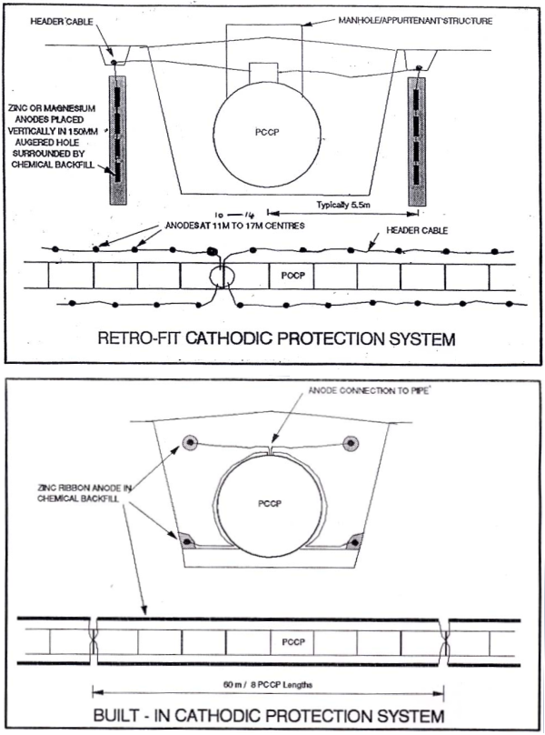
The cathodic protection system has been installed for the entire course of the Manmade River piping system using zinc strips or zinc or magnesium cathodic protection electrodes under the supervision of the Technical Center for Inspection and Corrosion Protection. The following drawing illustrates the cathode protection used for prestressed concrete pipes
Periodic monitoring work
In order to maintain the efficiency and stability of the cathodic protection system, it is necessary to periodically monitor the entire course of the Manmade River with a length of about 4000 km and to conduct the following tests:
• Measurements of static potential difference: By measuring the potential difference at each test point on the path of the system.
• Close-distance potential difference measurements: - by measuring the voltage difference of the pipe at every one meter, along the path of the system.
• Measuring the presence of stray currents along the path of the system.
• Measurements of soil resistivity.
• Measuring the currents circulating along the path of the system.
Evaluation of the level of cathodic protection
American specifications used numbers RP-100 2000 and RP-100-2004 in evaluating the effectiveness of cathodic protection, which stated that achieving 100 millivolts of decay or displacement is capable of stopping corrosion in metal wires for prestressed concrete pipes. The American standard is the only standard concerned with prestressed concrete pipes, and it's the only one that has a scientific basis based on the Tafel Plot based on the cathodic and anodic polarization of iron (Tafel Slop in EVAN Diagram), and on practical work (as this standard was used in the evaluation of a number of cathode protection systems for prestressed concrete pipes in the United States of America). The European standard BS EN 12696 2000 specializes in protecting the iron used in concrete of compounds which are exposed to the atmosphere only and does not deal with the protection of the concrete-iron buried underground, also other standards such as -710 millivolts which has a mathematical scientific basis based upon a (pH-E Potential Diagram) curve which determines if corrosion is possible or not, however, it does not address corrosion rates, therefore the center used the American standard in evaluating the level of cathodic protection for concrete piping systems. The center conducts instantaneous voltage difference surveys as well as measured voltage difference surveys after disconnecting cathodic protection systems for a period of 48 hours to determine the value of the decay potential difference for each station as follows:
The value of the decay potential difference = (the instantaneous potential difference in converging steps - the potential difference measured 48 hours after disconnection of the cathode protection system).
The steps involved in evaluating the results of the decay potential difference:
• Concentrating periodic monitoring on stations that do not achieve 100 millivolts, provided that some of them are selected to be monitored by the non-destructive monitoring technology available in the project for a period of at least two years, in order to know the ability of low cathodic protection levels to stop corrosion of the pre-stressed metal wires according to the agreement concluded with the American expert Sylvia Hall.
• Identification and selection of stations that have achieved a standard of 100 millivolts decay (at least 3) with cut wires previously identified by one of the non-destructive detection techniques and a complete test program for them includes and is not limited to the following: -
- Extraction of soil samples from the test stations and perform the following:
o Measurement of resistivity.
o Measuring the percentage of chloride ions.
o Measuring moisture content.
- Monthly measurement of the current coming out of cathodic protection basins.
- Measuring the declining and instantaneous voltage difference in converging steps annually.
- Examination of pipes with eddy current technology.
- Install audio monitoring stations on test stations.
Intersections and interference between cathodic protection systems
Interference tests are carried out with the oil companies' pipelines intersecting with the Manmade River pipelines periodically to avoid any interference or effect on the efficiency of the cathodic protection systems
Managing technical center data for inspection and corrosion protection
All engineering works of the Technical Center for Inspection and Corrosion Protection are linked with data management, as they were used to assess the condition of pre-stressed concrete pipes through the evaluation of the cathode protection system during the period of operation and maintenance, and due to the importance of the project, the significance of the database and its management increased, for taking the appropriate decision at the appropriate time.
Since the inception of the Technical Center for Inspection and Protection from Corrosion in the River, the interest in the Data Management Unit has begun, where the results of the surveys are converted into spreadsheets, Excel format, which can be drawn in one curve, regardless of the number of surveys for the same station, so that the amount of displacement or decay can be determined by the equations of the arithmetic tables. Over the past years, the data display has been developed, and the center’s experts had worked diligently to analyze it until we arrived at the current situation:
• All voltage difference surveys in converging steps, current strength measurement, resistivity, and soil information for any station can be displayed regardless of the number of surveys in one sheet containing several curves
• It is possible to determine the displacement or decay amount for the entire station only (600 meters) by calculating the rates of potential difference levels achieved in all station surveys and calculating the difference between them, but we could not determine the amount of displacement and decay at each pipe or for specific distances.
• All previous work in data management was limited to developing data display methods in spreadsheets and graphical curves.
• Data analysis work carried out by the center’s experts in the traditional way, therefore, we were not able to build a database that contains all the surveys and is equipped with programs to administer them, display their data and analyze them according to specific standards and distances starting from a single pipe length (7.5 meters) to large distances
In order to increase the efficiency of data management, work is underway to develop the database program, risk management and its inclusion of corrosion protection data by companies specialized in this field.
The future work of the Technical Center for Inspection and Corrosion Protection
• Carrying out maintenance work for the cathodic protection system vehicles that are exposed to attacks and the theft of their components.
• Conducting voltage difference tests in close steps to determine the condition of the pipes and ensure their protection for the project's systems.
• Follow up on preparing the equipment workshop at the center to conduct maintenance work for the devices and equipment used in the testing work.
• Follow-up of contracts for the implementation of the new cathodic protection on the project systems.